CNC TECHNICAL GUIDE
Phase, Neutral and Earth Explained: Wiring, Grounding, Testing & Safety
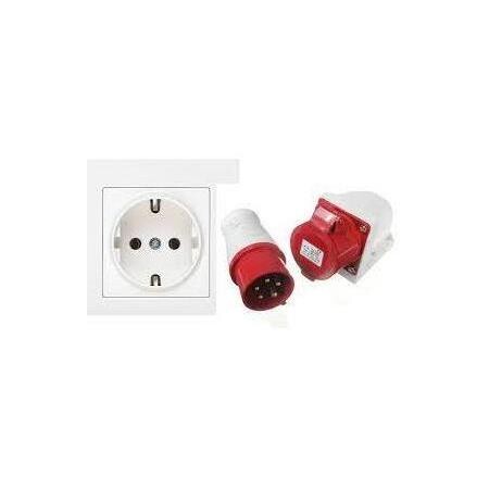
Phase, neutral and protective earth are not interchangeable conductors. They form different parts of an AC electrical system: the phase conductor supplies electrical energy, neutral normally provides the return path, and protective earth exists primarily for fault protection. This guide explains what each conductor does, how they work together, why neutral and earth must not be casually bridged, how grounding arrangements are designed, and what qualified personnel look for when diagnosing wiring problems.
This article is technical education, not a substitute for local electrical codes or a qualified electrician. Live electrical measurements, panel work and conductor identification can be fatal if performed incorrectly. De-energize, lock out and verify absence of voltage before work whenever the task permits. Industrial and three-phase systems should be inspected by competent personnel using approved procedures and test equipment.
What Are Phase, Neutral and Earth?
In a typical AC electrical installation, phase, neutral and protective earth perform different jobs. Their relationship determines how a load is powered, how the system establishes a voltage reference and how exposed conductive parts are protected during a fault.
A common but dangerous misunderstanding is to treat neutral and earth as if they were the same wire because they can be connected together at a designed point in the supply system. They are not the same conductor downstream, and they are not intended to perform the same function.
What Is Neutral?
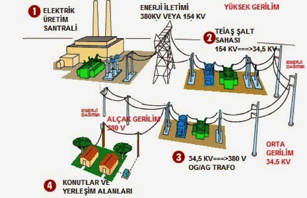
Neutral is a grounded circuit conductor used as a reference and normal current-return conductor in many AC power systems. In a common low-voltage distribution arrangement, the neutral originates from the star point of a transformer or generator winding and is intentionally referenced to earth at a controlled point.
When a single-phase load is connected between line and neutral, current flows from the line conductor, through the load and back through neutral. Neutral therefore carries current during normal operation. It must never be assumed to be harmless simply because it is expected to remain close to earth potential.
The basic function of neutral
- Completes the normal circuit for line-to-neutral loads.
- Provides a defined reference for many low-voltage distribution systems.
- Carries load current, including unbalanced current in many three-phase four-wire systems.
- Helps stabilize phase-to-neutral voltages when the system is correctly designed and intact.
Why neutral may not be at exactly zero volts
Neutral conductors have resistance and impedance. When current flows, a voltage drop can develop along the conductor. Loose connections, long cable runs, heavy loading, harmonics or a damaged neutral can increase the difference between neutral and local earth potential.
A neutral conductor can carry substantial current and may reach hazardous voltage under fault conditions. A broken or incorrectly connected neutral can create unexpected voltages on circuits that appeared normal before the fault.
Neutral in homes, workshops and industrial buildings
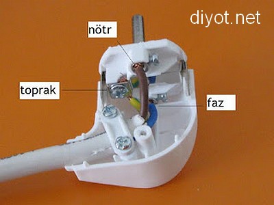
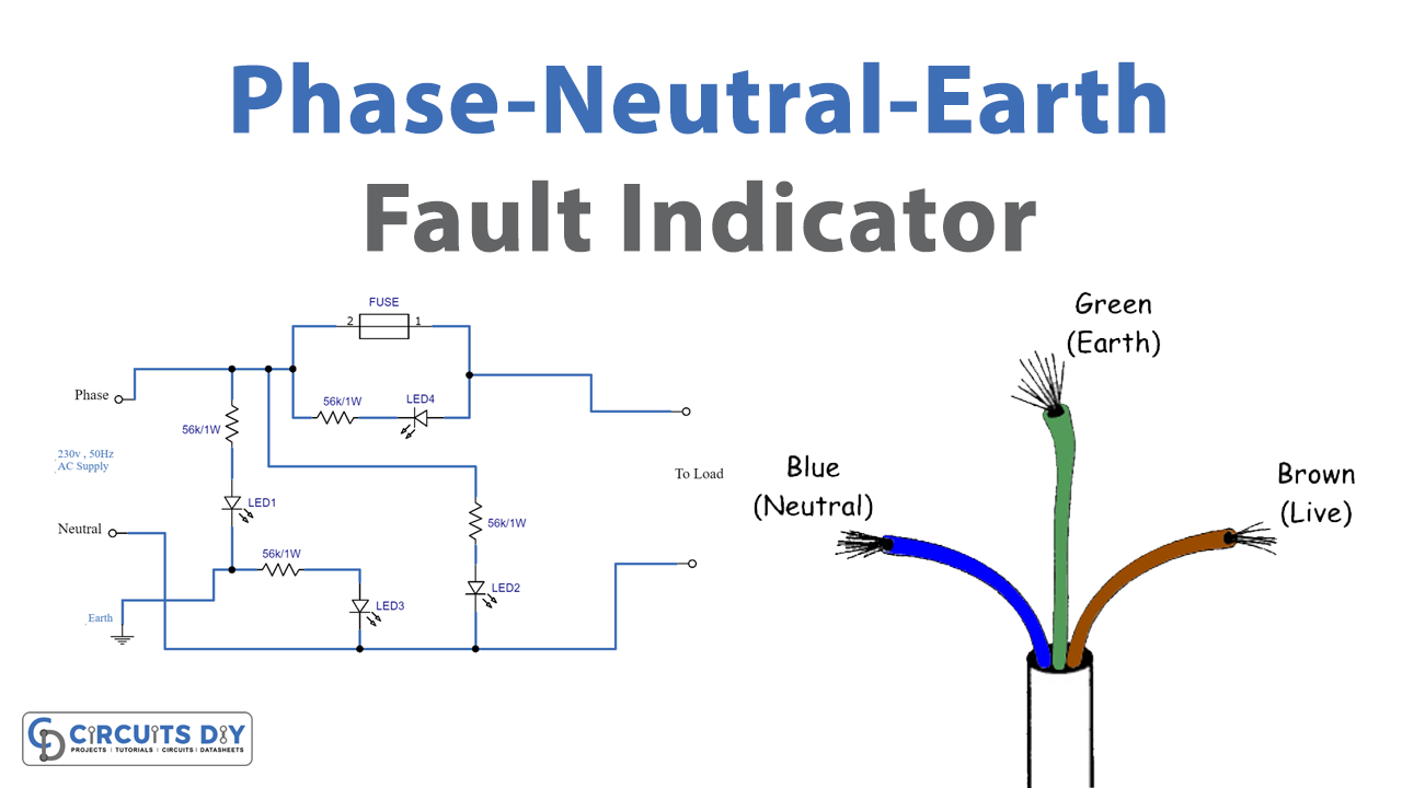
Under IEC-style color conventions, neutral is commonly blue. Older installations and installations built under other standards may use different colors. In a distribution board, neutral conductors are normally connected to a neutral bar whose relationship to protective earth depends on the earthing system and the point in the distribution network.
After the designated bonding point, neutral and protective-earth conductors are normally kept separate. The exact architecture depends on whether the installation uses TN-S, TN-C-S, TT, IT or another permitted earthing arrangement.
What Is the Phase / Live Conductor?
The phase conductor—also called line or live—carries the supply voltage to electrical loads. It has an alternating voltage relative to neutral and earth according to the distribution system.
In many European and Turkish low-voltage systems, the nominal single-phase line-to-neutral voltage is approximately 230 V AC. Three-phase systems typically provide approximately 400 V line-to-line, but actual nominal values depend on country, system and supply standard.
What the phase conductor does
- Transfers electrical energy from the source toward the load.
- Creates the operating voltage across line-to-neutral or line-to-line loads.
- Remains potentially hazardous whenever the circuit is energized, even if the connected equipment is switched off incorrectly or no current is flowing.
Common phase-conductor colors
Modern IEC-style installations commonly use brown, black and grey for phase conductors. Red and other colors may be found in older installations or other jurisdictions. Color is useful as an initial clue, but it is not proof of conductor function.
Repairs, renovations, non-standard wiring and older color schemes can make visual identification unreliable. Qualified testing and circuit documentation are required when conductor identity matters for safety.
What Is Protective Earth?
Protective earth, normally abbreviated PE, is a protective conductor connected to exposed conductive parts such as machine frames, motor bodies, electrical cabinets and appliance enclosures. Its purpose is not to serve as the normal return conductor for operating current.
If insulation fails and a live conductor contacts exposed metal, the protective conductor provides a low-impedance fault path appropriate to the system design. That fault current allows the relevant protective device—such as a fuse, circuit breaker or residual-current device—to disconnect the circuit within the required safety conditions.
Main functions of protective earth
- Bond exposed conductive parts into the protective equipotential system.
- Provide a controlled path for fault current.
- Support automatic disconnection of supply when a dangerous fault occurs.
- Reduce dangerous touch-voltage exposure when the protection system is correctly engineered.
Protective-earth conductor color
Under IEC conventions, the green/yellow combination is reserved for protective conductors. Older or non-IEC installations may differ. Again, color must not replace testing, documentation or competent inspection.
Normal load current should not be intentionally routed through the protective-earth conductor. If PE is carrying significant continuous current, the installation needs investigation.
How Do Phase, Neutral and Earth Work Together?
For a common single-phase load, the phase conductor supplies energy and neutral returns operating current. Protective earth sits outside that normal power path and becomes critically important when an insulation or bonding fault occurs.
| Conductor | Normal role | Current in normal operation? | Safety meaning |
|---|---|---|---|
| Phase / Line | Supplies voltage to the load | Yes, when the load draws current | Hazardous when energized |
| Neutral | Normal return / reference conductor | Yes | Must not be assumed touch-safe |
| Protective Earth | Fault protection / bonding | Normally no load current | Critical protective path during faults |
The protection concept works as a complete system. Correct conductor sizing, protective bonding, overcurrent protection, RCD/GFCI protection where required, earthing arrangement and fault-loop impedance must all be compatible.
How Are Neutral and Earth Identified?
Neutral and protective earth can look easy to distinguish in a new, correctly documented installation. In older buildings, modified workshops or improvised machinery, conductor colors may have been reused or connected incorrectly. For that reason, identification should combine documentation, visual inspection and appropriate testing by a competent person.
1. Cable color is only the first check
| Typical IEC function | Typical color | Important limitation |
|---|---|---|
| Neutral | Blue | Older wiring may use different colors |
| Protective earth | Green / yellow | Incorrect previous repairs can defeat the color convention |
| Phase | Brown / black / grey | Legacy installations may differ |
2. Visual inspection of outlets and cabinets
A visual inspection can show whether the green/yellow conductor appears to terminate on protective contacts and whether blue conductors appear to terminate on the neutral side. This is useful evidence, but it does not prove that the conductor is correctly connected all the way back to the distribution system.
What Can Electrical Measurements Indicate?
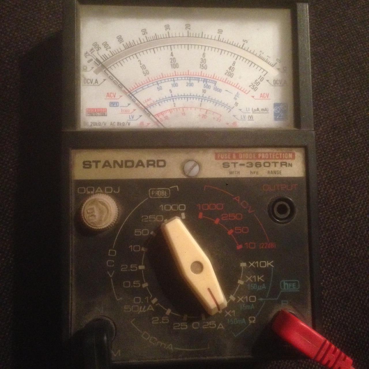
Qualified electricians use properly rated test instruments to confirm conductor identity, voltage relationships, continuity and fault-loop conditions. The original Turkish guide discusses line-to-earth, line-to-neutral and neutral-to-earth measurements; those relationships are useful, but individual readings are not universal pass/fail numbers.
Live probing exposes the operator to shock and arc hazards. Measurements should be performed only by competent personnel with correctly rated equipment, appropriate PPE and a safe method for the installation category.
Line-to-neutral voltage
In a 230 V-class single-phase system, a correctly operating line-to-neutral circuit is expected to be close to the nominal supply voltage. A materially abnormal reading can indicate supply, neutral, connection or loading problems.
Line-to-earth voltage
Where the earthing arrangement references the system to earth in the conventional way, line-to-earth voltage is generally expected to be in the same nominal range as line-to-neutral. However, the exact result depends on the earthing system and fault conditions.
Neutral-to-earth voltage
A small voltage can exist between neutral and local earth because neutral carries current and therefore experiences voltage drop. The original article cites values around 0–2 V as a typical healthy observation in some installations and flags larger values as a reason to investigate. That is not a universal limit: circuit length, load, conductor size, harmonics, bonding architecture and measurement location all matter.
A noticeably elevated neutral-to-earth voltage may indicate excessive neutral drop, a loose neutral, high load, poor bonding/earthing or an incorrect connection. It should be diagnosed in context rather than interpreted from one number alone.
Continuity and resistance checks with the installation safely de-energized
With the circuit isolated and proven dead, electricians may perform continuity testing of protective conductors. The original guide refers to very low resistance as desirable, but a simple handheld resistance number is not a substitute for the formal continuity, loop-impedance and protective-device tests required by electrical standards.
The important principle is that the protective path must have sufficiently low impedance and reliable continuity for the protection system to operate within its required disconnection time.
What Can Be Learned from the Distribution Board?
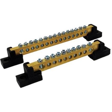
The distribution board often provides the clearest view of how the installation is structured. A qualified inspection can identify the neutral bar, protective-earth bar, incoming supply arrangement and the location—if any—of the neutral-to-earth bond permitted by the system design.
Protective-earth bar
Green/yellow conductors typically terminate here. The bar is bonded to the protective earthing system and, where appropriate, to the metal enclosure.
Neutral bar
Neutral conductors terminate here. Downstream of the designated supply bonding point, the neutral bar may need to remain insulated from the enclosure and PE bar according to the earthing arrangement.
A bridge inside a socket, junction box, machine or downstream panel can create parallel return-current paths, interfere with residual-current protection and energize exposed conductive parts under certain faults.
What Can RCD / GFCI Behavior Tell You?
A residual-current device compares current leaving and returning through the monitored live conductors. If the difference exceeds its trip threshold, it disconnects the circuit. A neutral-to-earth connection downstream of the RCD can allow current to bypass the monitored neutral path and cause unwanted tripping.
Repeated or apparently random RCD trips can be caused by many things: insulation leakage, moisture, EMI filters, multiple equipment leakage currents, damaged cables or neutral-earth faults. A trip pattern is therefore a diagnostic clue, not proof of one specific fault.
Bypassing or disabling an RCD because it trips is not a repair. The underlying cause must be identified.
Common and Dangerous Wiring Mistakes
- Bridging neutral and protective earth at an outlet because “both are near zero volts.”
- Using neutral as a replacement protective-earth conductor where a proper PE conductor is missing.
- Assuming blue or green/yellow insulation proves the conductor is correctly connected.
- Defeating an RCD/GFCI instead of investigating the leakage or wiring problem.
- Leaving loose neutral connections that overheat or create unstable circuit voltages.
- Working on industrial or three-phase equipment without isolation, lockout and competent testing.
When professional help is essential
Use a qualified electrician or competent industrial electrical technician if the installation is old or undocumented, protective earth is missing, voltage readings are unstable, an RCD repeatedly trips, conductors cannot be positively identified, or the system includes industrial three-phase machinery.
What Is Neutral Grounding?
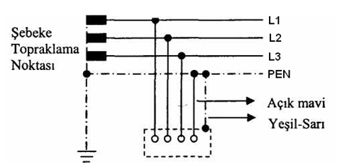
Neutral grounding is the intentional connection of a system neutral point to earth through a defined method. It is an engineered system decision, not an improvised connection made anywhere a neutral conductor happens to be available.
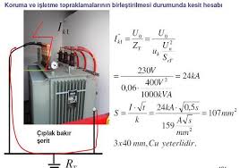
In many three-phase sources, the common point of star-connected windings forms the neutral point. Grounding this point establishes a defined relationship between the power system and earth, influences earth-fault current and supports the protection strategy.
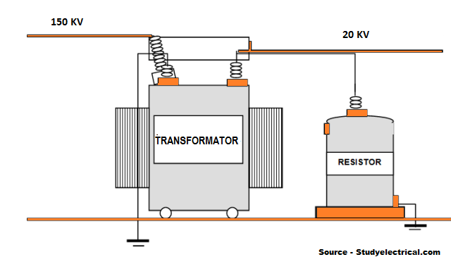
Where neutral grounding is commonly implemented
- At generators or power sources where a neutral point is created.
- At distribution transformers, commonly at the star point of the secondary winding.
- At designated service or system bonding points permitted by the local code.
- Through grounding impedance in industrial systems designed to limit earth-fault current.
Why ground the neutral?
A correctly designed grounding method gives the system a defined reference to earth and determines how it behaves during an earth fault. It helps protection engineers coordinate fault-current magnitude, overcurrent devices, earth-fault relays, insulation requirements and transient overvoltage behavior.
The grounding conductor itself does not “magically absorb” lightning or all surges. Surge-protective devices, bonding, insulation coordination and the overall earthing system work together to manage transient events.
Common Neutral Grounding Methods
Different industrial systems use different grounding methods because fault-current magnitude, process continuity and protection requirements vary.
Solid grounding
In a solidly grounded system, the neutral point is connected to earth without an intentional current-limiting impedance. Earth-fault current can therefore be relatively high, allowing conventional overcurrent or earth-fault protection to operate rapidly when the system is designed accordingly.
- Advantages: simple concept, defined phase-to-earth voltages, strong fault signal for protection.
- Trade-offs: higher fault current can increase thermal and mechanical stress at the fault location.
Resistance grounding
A neutral-grounding resistor is inserted between the neutral point and earth to limit earth-fault current. Low-resistance and high-resistance grounding schemes are used for different industrial objectives.
- Advantages: controlled earth-fault current, reduced fault damage in suitable systems, easier fault monitoring when engineered correctly.
- Applications: industrial plants where process continuity and fault-energy limitation are important.
Reactance grounding
An intentional reactor is installed between neutral and earth to limit or shape earth-fault current. This method requires protection coordination and system calculations and is not a general-purpose substitute for solid grounding.
The neutral-ground relationship belongs to the power-system design. A downstream bridge can create dangerous touch voltages, parallel current paths and protection problems.
Why Phase, Neutral and Grounding Matter for CNC Machines
CNC routers and industrial machines combine high-power loads with sensitive electronics. Spindle inverters, servo drives, stepper drives, PLCs, motion controllers, computers, sensors and communication networks can all share the same machine frame and electrical cabinet.
Protective bonding of the machine
Exposed conductive parts should be bonded into the machine protective-earth network according to the manufacturer’s electrical design. That typically includes the electrical enclosure, metal machine structure, motor/spindle bodies where applicable and designated PE terminals.
VFDs and leakage current
Variable-frequency drives use fast-switching power electronics and often include EMC filtering. This can produce high-frequency common-mode currents and normal leakage to earth. Cable type, shielding, grounding, filter design and RCD selection must therefore be compatible with the drive manufacturer’s requirements.
Signal reference is not the same as protective earth
Control-system 0 V, cable shield termination, chassis bonding and protective earth serve different electrical purposes. They may be connected at defined points, but they should not be mixed arbitrarily. Good EMC design depends on intentional bonding architecture.
If you are planning a machine installation, also review our CNC Router Maintenance Checklist and CNC Support & Commissioning guide.
Frequently Asked Questions
Is neutral the same as earth?
No. Neutral is a normal current-carrying circuit conductor in many systems. Protective earth is a protective conductor intended primarily for fault conditions and bonding.
Can neutral give an electric shock?
Yes. Neutral can carry load current, can develop voltage drop and can become dangerously energized during wiring faults or an open-neutral condition.
Should protective earth carry current during normal operation?
It should not be used as the normal load-current path. Some equipment can have small leakage currents because of filters and capacitive coupling, but significant or unexpected PE current should be investigated.
Why is neutral connected to earth at all?
The intentional system connection establishes a reference to earth and determines fault-current behavior so the protection system can be designed and coordinated.
Can neutral and earth be joined in a socket?
Not as an improvised substitute for a proper protective conductor. The permitted bonding point is defined by the supply earthing system and local electrical code.
What does a high neutral-to-earth voltage mean?
It can indicate neutral voltage drop, loading, loose connections, grounding/bonding problems or other faults. One reading alone is not enough to diagnose the cause.
Why does an RCD trip when neutral and earth are linked downstream?
Some return current can bypass the monitored neutral conductor through the earth path, creating a current imbalance that the RCD detects.
Is wire color enough to identify conductors?
No. Color is an important convention but older wiring, repairs or incorrect installation can make it unreliable. Documentation and competent testing are needed.
English full-scope edition based on the CNC Marketi Turkish knowledge article “Nötr, Faz ve Toprak Nedir?”. The English edition preserves the source topic scope while clarifying safety-critical statements for an international audience.